1. Technical Principles: Why is UV "Cold Laser" the Standard for Crystal Engraving?
3D crystal subsurface engraving is extremely sensitive to thermal effects. According to Cloudray's technical architecture, this equipment utilizes UV Cold Laser Processing technology. Compared to Fiber or CO2 lasers, UV light sources possess a much shorter wavelength and a significantly reduced Heat Affected Zone (HAZ), perfectly solving two major processing challenges:
-
Eliminating Thermal Damage: Effectively prevents micro-cracks or scorching on Heat-sensitive Materials caused by high temperatures.
-
High-Transparency Penetration: Specifically designed for Transparent and Brittle Materials (like crystal and glass). It ensures the laser penetrates the surface to create precise micro-burst images internally without damaging the exterior.
2. Key Hardware Configuration
To achieve micron-level engraving precision, the optical path system has been optimized with specific enhancements:
-
Optical System: Features a built-in 10X Beam Expander. This compresses the laser spot to its limit, drastically improving the fineness and resolution of the internal point cloud.
-
Temperature Control: Equipped with Industrial Water Cooling. This ensures power stability under high-frequency pulsing and prevents light decay (power loss) during long-duration operations.
3. Operation Tutorial: 7 Steps to Perfect 3D Crystal Engraving
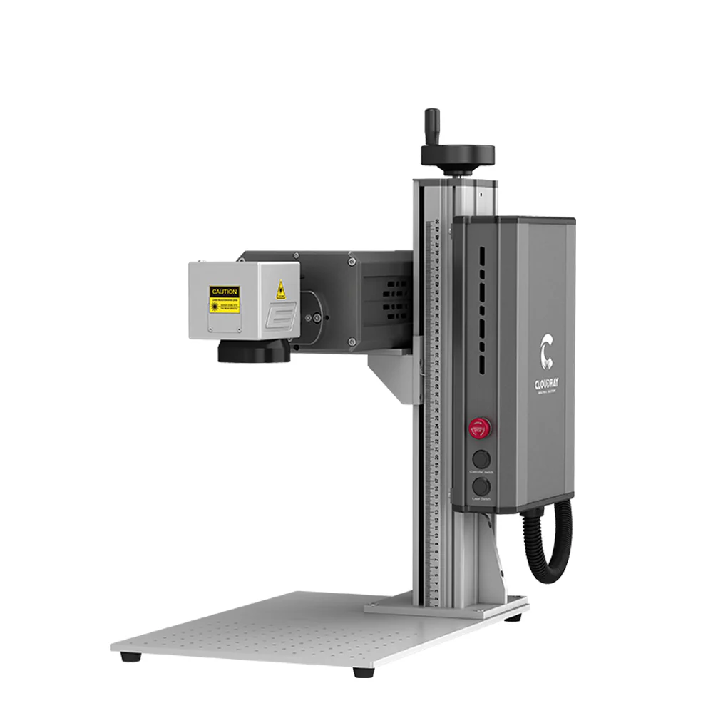
The following workflow is based on the Cloudray-CAD control software and is optimized for the Cloudray UV-P-5 series models.
Step 1: Model Import
Launch the Cloudray-CAD software and click the "Internal Carving" icon on the toolbar. The software natively supports mainstream 3D formats such as .obj or .stl, requiring no additional format conversion.
Step 2: Real-World Measurement (Crucial)
Crystal crafts often have a manufacturing tolerance of 1-2mm. Do not rely on theoretical dimensions.
-
Action: Use a ruler to precisely measure the actual X (Length), Y (Width), and Z (Height) of the crystal block.
-
Input: Enter these real-world values into the "Crystal Size" panel on the left. The software will reconstruct a virtual processing space that corresponds 1:1 with your physical object.
Step 3: Layout & Safety Margins
-
Center Alignment: Adjust the model's Position/Offset in the virtual space to ensure the subject is perfectly centered within the crystal.
-
Safety Padding: Ensure there is a physical buffer distance between the model's edge and the crystal's boundary. This prevents the crystal from shattering due to excessive edge stress.
Step 4: Texture & Quality (Layer Settings)
-
Key Parameter: Locate the "Marking Layers" option.
-
Pro Tip: This parameter directly controls Point Cloud Density. Higher layer counts result in denser internal micro-bursts, increasing the finished product's "Whiteness" and Opacity, thereby enhancing the 3D visual effect.
Step 5: Physical Focusing (The 100mm Golden Rule)
This is the most critical physical calibration step. While the machine may have auto-focus, manual physical focusing provides the most reliable baseline for subsurface engraving.
-
Action: Open "Motion Axis Settings".
-
Measure: Use the Z-axis to raise/lower the laser head. Use a steel ruler to measure the vertical distance from the bottom edge of the lens to the top surface of the crystal.
-
Standard: Strictly lock this distance at 100mm.
-
Finalize: Once calibrated, click "Set Zero" to lock the focal point.
Step 6: Red Light Preview (The White Paper Method)
Because UV laser red light indicators penetrate transparent materials, the preview box is often invisible to the naked eye.
-
Hack: Place a piece of white paper on top of the crystal surface.
-
Verify: The red light will project clearly onto the paper, allowing you to confirm if the engraving area is centered.
-
Warning: You must remove the white paper before starting the actual marking process.
Step 7: Execution
Verify that the water cooling system is running normally, then click the "Marking" button in the software. The machine will automatically complete the subsurface engraving along the preset path.
4. Extended Applications & FAQ
Q: Beyond crystal engraving, what other materials can this device handle? A: This highlights the versatility of UV lasers. Beyond glass and crystal, it is ideal for:
-
Plastics & Rubbers: Especially ABS, PVC, and Silicone. It is perfect for fire-retardant engineering plastics as it marks without yellowing or burning.
-
Heat-Sensitive Films: Such as soft packaging for food or cosmetics. UV light can remove surface coatings without damaging the substrate.
-
Metals (Specific): While primarily for non-metals, it excels in applications requiring touch-free, high-contrast black marking or oxide removal on electronic components.
Q: Why is UV Laser better than Fiber Laser for plastics or glass? A: The core difference is the Thermal Effect.
-
Fiber Lasers (1064nm) rely on heat to ablate material, which often causes plastics to turn yellow/burn or causes glass to shatter.
-
UV Lasers (355nm) utilize "Cold Processing." They break chemical molecular bonds to change color or remove material with almost no heat generation. This results in damage-free materials with smooth, burr-free edges.
Q: Will markings on medical devices rub off? A: No. UV laser marking creates a permanent physical/chemical change. It is resistant to alcohol wiping, high temperatures, and high-pressure sterilization, making it fully compliant with strict medical industry standards (UDI).